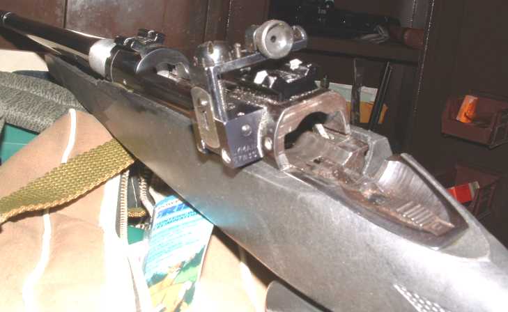
For my level of shooting, I can't justify the cost of match type sights with separate bases, etc. So I mounted a Williams Foolproof peep sight. I mounted the sight as per instructions, drilling and tapping the Savage receiver.
If I removed the rear scope base I could use the sight with a standard sporter type front sight. I didn't like the idea of frequently removing the glass beded Weaver base so I elected to use an elevated front sight and leave the scope base undisturbed. Unfortunately, this means that the sight bridge sticks way up above, giving little elevation adjustment. What I decided I needed was an aperture sight that attached directly to the Weaver base in the first place.
As it turns out NECG makes a hunting type sight that does just this, but it is fairly pricey and doesn't have the click type adjustment knobs. There are also a few match type sights that do the same thing - but these are really expensive. I decided to make and adapter that I would mount a standard type receiver sight to and that would then clamp to the weaver base.
An Easy Home Gunsmithing Project
After a few mistakes, I was able to put together an adapter
from a scope ring and piece of angle iron fairly easily. The result looks alot
like the match sights and works well. The sight aperture is to the rear of the
rifle, near where a scope eyepiece would be. This means that the head position
used for iron sights is about the same as for scope sights so that no stock
alterations or change in shooting style is required.
This also turns out to be a good first home gunsmithing project for the following
reasons:
- All metal work is off the gun. You are not drilling/tapping
your receiver so you don't have to worry so much about goof ups.
- Drilling and tapping will be aluminum scope rings or mild
steel angle iron.
- Careful measurements and marking will pay off with good
results.
The trick with this project, and most gunsmithing projects, is to carefully measure and mark as you go along before cutting and drilling. As you will see below, it is easier to measure and mark as you go along compared to measuring and marking all up front. That way you can compensate for inaccuracies in measurements as you go along.
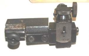
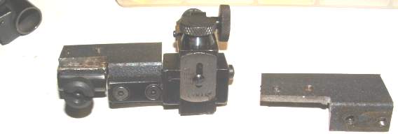
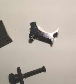
Here is the finished sight next to a first attempt where I mounted the sight
too high on the angle iron - see where the sight holes are in relation to the
holes on the finshed adapter-
Tools and Materials
A hacksaw is required for cutting and trimming angle iron to
size. Other tools required are the basic minimum for any type of gunsmithing
task. A drill (drill press is best, but this project can be done with a hand
drill), a vise to hold material, hand files, drills, tap, tap holder and countersink.
A marking tool (scribe - or can be a sharp pointed nail) is also required along
with either a good ruler or calipers for measuring. 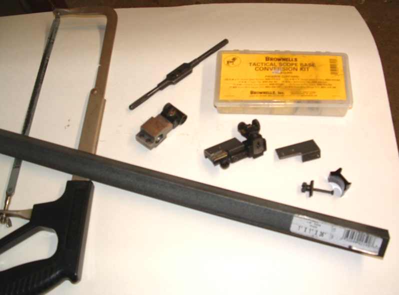
 I
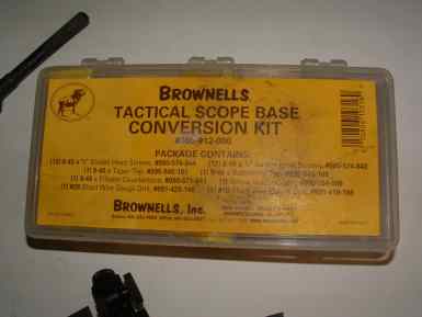
have pretty much standardized on the 8-40 screw size for drilling and tapping.
It is the strongest of the sight screw sizes and the larger tap is less susceptible
to breakage compared to a 6-48 tap. Brownells.com sells a "Tactical Sight
Base" kit for converting sight base mounts to the stronger 8-40 screws.
It has taps, drills, fillister type screws and matching piloted countersink
and even has a holder for grinding down screws to fit. In this application other
sizes are okay, and you may wish to use the size screws supplied with the peep
sight you use. Just remember, for every screw size you will need a clearance
drill, pilot drill and tap. (The pilot hole is sized for the threads to be cut
by the tap.) Depending on screw head profile (e.g. fillister), you may also
need a separate countersink as well.
I
have pretty much standardized on the 8-40 screw size for drilling and tapping.
It is the strongest of the sight screw sizes and the larger tap is less susceptible
to breakage compared to a 6-48 tap. Brownells.com sells a "Tactical Sight
Base" kit for converting sight base mounts to the stronger 8-40 screws.
It has taps, drills, fillister type screws and matching piloted countersink
and even has a holder for grinding down screws to fit. In this application other
sizes are okay, and you may wish to use the size screws supplied with the peep
sight you use. Just remember, for every screw size you will need a clearance
drill, pilot drill and tap. (The pilot hole is sized for the threads to be cut
by the tap.) Depending on screw head profile (e.g. fillister), you may also
need a separate countersink as well.
In addition to screws (2 for the sight and two to attach the angle iron to the altered scope ring), you will need a 4" piece of angle iron (1 inch to 2 inch size - available at Home Depot) a scope ring (low height recommended) and an appropriate receiver sight. For a receiver sight I got a Lyman 57 on ebay. (It came used without screws but I redrilled the holes for 8-40s anyway.) It is the type with the mounting extension. As seen below, the sight profile needs to be filed flat to mate with the angle iron and the extension is a smaller piece to have to file. A sight for a flat sided rifle may be even more advantageous.
NOTE: Some peep sights mount from the left, some from the right. Obviously which side you are working from will depend on the sight you use. It is recommended that you position the scope ring used so that the mount nut is opposite of the sight. It is not recommended that you use sights that attach on the top - they may end up too high comfortable use.
Step 1- Drill one hole center line of scope ring:
You may want to begin step 2 first, but what you will need to
do is mark the scope centerline at the bottom part of the scope ring top surface,
and drill a hole on that center line. The hole must miss the slot for the cross
bolt as follows.
 Disassemble
the scope ring, discarding the top part of the ring. Remove the cross bolt and
side clamp. On the bottom of the ring, measure the distance from the front edge
of the ring to the front edge of the cross bolt slot and write it down. Clamp
the scope ring bottom in a vise so that it is horizontal, using a level if possible.
Scribe a line with a straight edge at the very bottom of the curved portion
of the rings. This line should match up with the center line of a scope that
would be mounted in the rings.
Disassemble
the scope ring, discarding the top part of the ring. Remove the cross bolt and
side clamp. On the bottom of the ring, measure the distance from the front edge
of the ring to the front edge of the cross bolt slot and write it down. Clamp
the scope ring bottom in a vise so that it is horizontal, using a level if possible.
Scribe a line with a straight edge at the very bottom of the curved portion
of the rings. This line should match up with the center line of a scope that
would be mounted in the rings.
 Measure
from the front edge of the ring a distance of one-half
the distance measured above from the front edge to the cross slot on the bottom
of the ring. Center punch at that distance directly on the center line. Carefully
drill a hole down through the base using a clearance sized drill. Turn the ring
upside down and counter sink the bottom of the ring for the mounting screws
to be used.
Measure
from the front edge of the ring a distance of one-half
the distance measured above from the front edge to the cross slot on the bottom
of the ring. Center punch at that distance directly on the center line. Carefully
drill a hole down through the base using a clearance sized drill. Turn the ring
upside down and counter sink the bottom of the ring for the mounting screws
to be used.
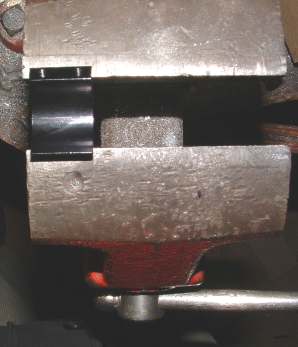
Step 2- File Scope Ring Flat:
The scope ring will mate the adapter with the Weaver base, so
the rounded portion that normally supports the scope has to be removed and the
remaining surface filed flat. I used an aluminum cast off ring and using the
biggest file I own, filed it flat in no time. If your cast off is a better quality
steel ring you may want to trim with the hacksaw first.
Using a straight edge to check, make the top surface a smooth and level as you can. For the following measurements, mount the modified ring on the rifle.
Step 3 - Measure and Cut Adapter to Length
On your rifle, determine at what location you want the peep sight to be positioned.
As with a scope, you must have enough eye relief so that recoil doesn't push
the aperture into your eye. A rule of thumb for most bolt action rifles is even
with the bolt cocking piece. If the scope ring overhangs the mount in the front,
(i.e. towards muzzle) attach it to the rifle for the next measurement.
Measure, in a straight line, the distance from the front of the scope base or ring, to the desired position of the sight. Write this distance down.
Look at the screw mounting holes for the sight in relation to the aperture. You may need to lengthen the adapter in order to accommodate the mounting screws. Alternately you may be able to shorten the adapter if the screw holes are forward of the adapter. Leave at least an additional 1/4 inch beyond any screw hole for strength. With the Lyman sight I used, I purposely made the adapter only as long as it had to be in order to avoid cutting to provide elevation clearance for the sight.
Taking into account any adjustments, cut the angle iron to length.
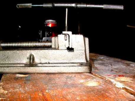
Step 4 - File Peep Sight Mounting Surface Flat:
Assuming you are using a sight designed for a round receiver,
hold the sight in the vise and file the area that will be contacting the adapter
flat. (Remove the aperture before clamping in the vise.) Take care to make it
as level as you can other wise the sight will be canted when you are done.
 Note
that with the sight I chose, I only had to file the mounting extension flat
as only that portion of the sight contacted the angle iron.
Note
that with the sight I chose, I only had to file the mounting extension flat
as only that portion of the sight contacted the angle iron.
Step 5 Determine Sight Mounting Height:
On your now modified sight, adjust the aperture all the way
down. Holding the sight flush with the end of the angle position it so that
the bottom of the aperture is even with the top of the angle iron. Put a mark
to indicate the vertical position of the the site mounting holes. With a straight
edge, scribe a line parallel with the top of the angle iron at the desired position
of the sight mounting holes.
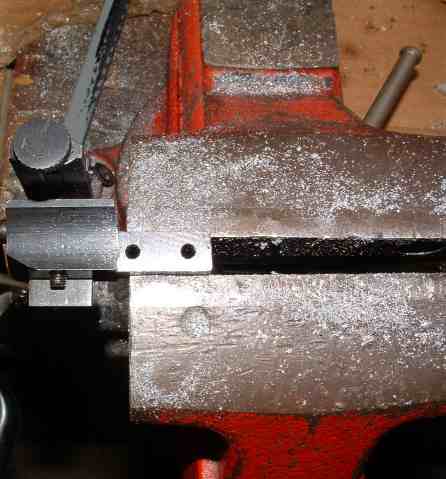
Step 6 Cut angle iron to provide clearance:
In order to mount the sight, it may be necessary to cut the
top off the angle iron for a section were the sight will be mounted. Mark it
and hacksaw off the interfering area.
Depending on the size angle iron used, it may be necessary to cut the vertical portion to provide clearance for the sight adapter to fit on the rifle. Place the angle iron over the rifle and verify that even when located well over the modified ring, it will not touch the rifle action. Mark the area of interference and hacksaw off a strip along the entire length of the iron to provide generous clearance.
Step 7 Mount sight on angle iron:
The procedure is the same as you would use to mount the receiver
sight on the rifle itself. Clamp the angle iron in a vise and locate the sight
where you want it to be. You should be able to see the line scribed in the step
where you determined desired sight height. Mark the spot for one of
the mounting screws on the line. Take away the sight, then center punch the
spot, making sure you are dead on the scribed line. Drill a pilot hole, and
tap the hole for the mounting screw (in my case 8-40). Just a reminder, use
plenty of oil, reverse the tap rotation frequently to clear chips and never
force a tap. Try to keep the tap as close to vertical as possible. The soft
steel in the iron angle is very easy to tap.
Mount the sight with the one screw and position it tightly so that the remaining screw hole is divided by the scribed line. Rather than using a punch (even the correct transfer punch) I have had good results by using a clearance drill (mounted in a light hand drill works okay) to just provide a starting mark. Position the drill in the hole and just give the drill motor a jog. The tip of the drill will break the surface right in the center of the screw hole. Switch to a pilot drill and drill and tap as before. Completing the mounting of the sight. Use plenty of loctite to make sure the sight doesn't shift.
Step 8 Establish Sight Center Elevation Line:
Adjust the sight elevation adjustments to dead center. Scribe
a line the length of the angle iron even with the sight aperture. This line
will match up with the center line in the modified scope ring.
Step 9 Provide clearance to mount onto modified scope
ring:
Locate the angle iron over the modified scope ring so that the
scribed line lines up with the hole already drilled. If you cant locate the
angle iron over the modified scope ring because the sides interfere, the interfering
sides must be hack sawed off.
Step 10 Mount angle iron onto modified scope ring:
Measure the distance determined in step 1 (one half ring edge
to slot edge) from the front of the angle iron and center punch exactly on the
center line. Drill a pilot hole and tap for a mounting screw.
Remove the ring base from the rifle and flip it over so that the angle iron can be mounted. While the the ring base is turned over, measure the distance from the one hole in the bottom of the base to the center of the base on the other side of the mounting bolt slot. Measure along the sight line on the angle iron from the hole that we just drilled and taped and center punch and pilot drill at that point. Do not tap this hole yet.
Bolt the two pieces together using the one screw hole and mount the entire assembly on the rifle. Make any adjustments as necessary to make sure everything lines up straight. Using the hole drilled as a guide use the pilot drill to start a hole in the modified ring. Separate the two pieces again and drill through the ring with a clearance drill counter sink the bottom side as before. Tap the pilot hole in the angle iron.
Step 11 Final assembly and measurement:
At this point you are finished with drilling and taping operations.
You may want to dissemble all pieces and with a fine file smooth all the rough
edges. The angle iron can be spray painted flat back for appearance purposes.
Then epoxy can be dabbed around the screw holes and on mating surfaces and the
entire assembly bolted together on a more or less permanent basis.
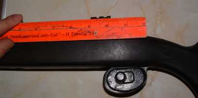
The last step is to mount the sight and measure the sight height from the bore
center line. This measurement will be needed to determine the front sight to
be purchased or fabricated.